Sequence Diagram
Overview
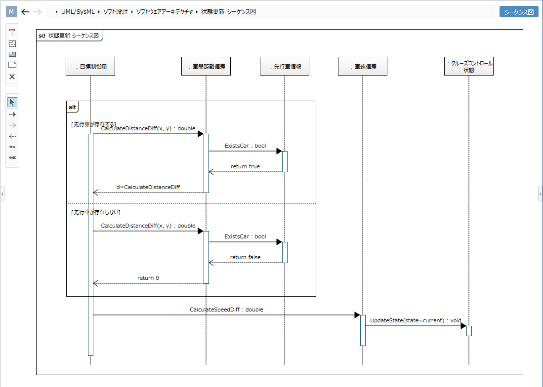
Sequence diagrams can be used to visualize the flow of mutual processing between objects. This page describes the operations for using the sequence diagram in the following order.
- Place a sequence diagram
- Define a lifeline
- Define a message
- Define a compound fragment
- Define the use of interactions
It also provides the following features to assist in user modeling: These will also be explained in order.
- Validate the model
- Set the display contents
Place a sequence diagram
To place the sequence diagram, follow the steps below.
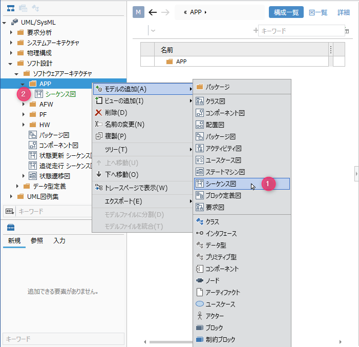
Operation procedure
- Select the package in the model navigator and click Add Model> Sequence Diagram in the context menu.
- The sequence diagram is placed as a child element of the selected package.
Define a lifeline
To define a lifeline, do the following:
Operation procedure
- Select an existing class in the Model Navigator and drag and drop it onto the sequence diagram.
- A new lifeline with the selected class as the type will be created in the displayed sequence diagram.
Elements that can be added from the toolbox
You can add the following elements displayed in the toolbox in the sequence diagram.
| Icon | Name |
|---|---|
 | Lifeline |
 | Composite Fragment |
 | Use of Interaction |
 | Interaction Note |
 | Destruction |
Define a lifeline with no type set
You can create an untyped lifeline by dragging and dropping [Lifeline] from the toolbox onto the sequence diagram.
tip
To change the lifeline type, select the lifeline on the sequence diagram and click [Change Lifeline Type] in the context menu.
Lifeline types that can be set The following elements can be specified for the lifeline type.
| Icon | Name |
|---|---|
 | Class |
 | Interface |
 | Components |
 | Actor |
 | Block |
Define a message
To define a message, do the following:
Operation procedure
- In the sequence diagram, when you mouse over the lifeline, a black triangle icon will be displayed.
- Drag and drop the displayed icon toward the target lifeline.
- When the finder is displayed, select the operation corresponding to the message and click the [OK] button.
- A sync message to the target lifeline is created.
Elements that can be added from the toolbox
In the sequence diagram, you can add the following elements displayed in the sub toolbox.
| Icon | Name |
|---|---|
 | Synchronized message |
 | Asynchronous message |
 | Reply Message |
 | Generated message |
 | Discard message |
When adding these messages, select the type of message you want to add in the sub toolbox, then add the message.
About the text notation of messages
When you enter text for a message operation on a sequence diagram, the text is parsed according to the notation format of the message operation. Of course, if you change each field value, it will be reflected in the text on the figure.
Correspondence between the text notation format of the message and each field value The message is displayed and parsed as text according to the following format.
- For request messages (other than response messages)
<Request message> :: = <Message name> ['('[<list of arguments>]')'] [':' <Return type>]- supplement
<List of arguments>is displayed in the following format.<list of arguments> :: = <arguments> [',' <arguments>]*<Argument> :: = [<Argument name>'='] <Argument value> |'-'
- example
Message name:Drive
Argument 1 name:m, value:100
Argument 2 name:s, value:200
Return type:boolean
In the case of, the following text will be displayed.Drive (m = 100, s = 200): boolean - Note
<Return type>is ignored when set.
- supplement
- For response messages
<Response message> :: = [<Return value variable name>'='] <Message name> ['('[<Argument list>]')'] [':' <Return value>]- supplement
<List of arguments>is displayed in the following format.<list of arguments> :: = <arguments> [',' <arguments>] *<Argument> :: = [<Argument variable name>'='] <Argument name> [':' <Argument value>]
- example
Variable name of return value:return_value, value of return value:true
Message name:Drive
Variable name of argument 1:miles, argument name:m, value:200
Variable name of argument 2:speed, argument name:s, value:100
In the case of, the following text will be displayed.return_value = Drive (miles = m: 200, speed: s = 100): true
- supplement
tip
To change the action that corresponds to the message, select the message and click Change Message Type in the context menu.
Define a compound fragment
To define a composite fragment, do the following:
Operation procedure
- Select the composite fragment in the toolbox and drag and drop it onto the sequence diagram.
- Double-click on the upper left of the added compound fragment to display a drop-down list of types and select the type of compound fragment to add.
List of compound fragment types
You can set the following types of composite fragments:
| Kind | Meaning |
|---|---|
| alt | Alternative |
| opt | Option |
| loop | Loop |
| par | Parallel |
| break | Break |
| neg | negation |
| strict | strict |
| seq | seq |
| ignore | ignore |
| consider | Consider |
| assert | Assert |
Define the use of interactions
To define the use of interactions, do the following:
![Add from the toolbox and reference in [Interaction Association] in the context menu](/support/documents/2.0/manual/en/assets/images/sequence-diagram-add-interactionuse-a5f62188b7bc8e91f3f4a2d484f1cd41.gif)
Operation procedure
- Select Use Interaction in the Toolbox and drag and drop it onto the sequence diagram.
- Select Use of the added interaction and associate the sequence diagram referenced in Interaction Association in the context menu.
tip
To jump to the sequence diagram associated with the use of interactions, select Use Interactions and click Show Associated Interactions in the context menu.
Validate the model
The contents verified in the sequence diagram are as follows.
- Is the operation associated with the message available for the lifeline type of the destination?
info
For example, you can detect inconsistencies between the operations associated with a message and the lifeline type of the destination as a result of making the following changes:
- For the operation associated with the message, specify the operation defined in the inheritance source class of the class that is the type of the lifeline of the destination.
- Delete the inheritance relationship of the class that is the type of the destination lifeline in the class diagram.
To validate your model, do the following:
Operation procedure
- From the ribbon, run UML> Verification> Check Consistency.
- If an inconsistency is detected in the message placed in the sequence diagram, an error will be displayed.
tip
Click the Home> Model> Check Error button on the ribbon to perform validation on all models in addition to standard validation.
Set the display contents
You can display only the information you are interested in in the sequence diagram without changing the model. To set the display content of the argument corresponding to the request message, follow the procedure below.
Operation procedure
- Display the sequence diagram for which you want to switch the display.
- Toggle the check box for the argument check box in the Request Message group on the UML Diagram tab of the Inspector.
Elements that can switch the display
You can switch the display of the following elements in the sequence diagram.
| Category | Elements |
|---|---|
| Request message | Arguments |
| Argument name | |
| Return type | |
| Response message | Arguments |
| Argument value | |
| Argument assignment variables | |
| Return value | |
| Return variable |
Restrictions
- State invariants and duration constraints cannot be defined.
- You cannot connect messages from frames.
- Messages cannot be connected to take advantage of interactions.
- You cannot copy and paste elements.
- The message ordering in the sequence (commonly referred to as GeneralOrdering) is represented only by the Y coordinate on the diagram. If you use the difference comparison function, you cannot check the difference as a model.
- Stereotypes are not represented on the sequence diagram.