Component Diagram
Overview
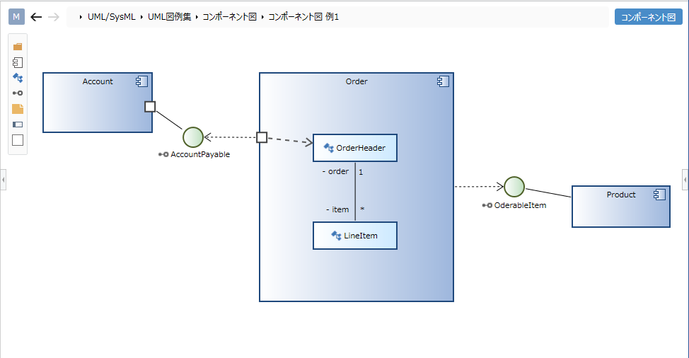
Component diagrams can be used to describe the internal structure of components and the relationships between them. This page describes the operations for using the component diagram in the following order.
- Place the component diagram
- Define a component
- Define associations
It also provides the following features to assist in user modeling: These will also be explained in order.
- Set the display contents
Place the component diagram
To place the component diagram, do the following:
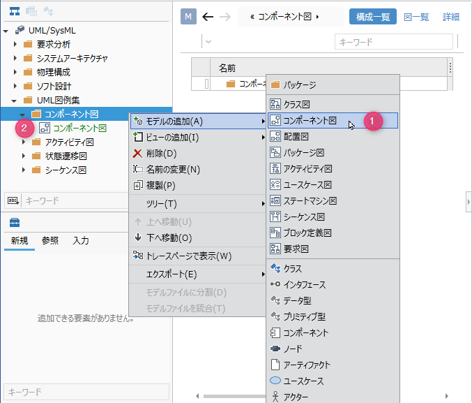
Operation procedure
- Select a package in the model navigator and click Add Model> Component Diagram in the context menu.
- The component diagram is placed on the child elements of the selected package.
Define a component
To define a component, do the following:
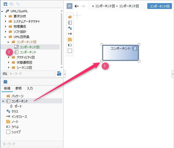
Operation procedure
- Drag and drop [Component] from the toolbox onto the displayed component diagram.
- The component is placed on the sibling element of the displayed component diagram.
Elements that can be added from the toolbox
In the component diagram, you can add the following elements that are displayed in the toolbox.
| Icon | Name |
|---|---|
 | Package |
 | Components |
 | Port |
 | Class |
 | Interface |
 | Note |
 | Labels |
 | Shape |
Arrange the ports as port shapes for the following elements:
- Components
Add stereotypes to components
To add a stereotype, do the following:
Operation procedure
- Select a component.
- Click the Add button in the Basic information> Stereotype field in the Property inspector to see the choices.
- Select a stereotype and press the OK button to set the stereotype for the component and display the stereotype at the top of the shape.
tip
Stereotype choices can be defined in the Detail view of the package model.
tip
You can edit the added stereotype from the component diagram by following the steps below.
- Double-click the stereotype displayed on the component to enter the edit state.
- If you change the stereotype and confirm the edit, it will be reflected on the component diagram and the stereotype of the component will be changed.
tip
- If you want to display an existing component on the component diagram, you can display it by dragging and dropping the component on the model navigator onto the component diagram.
- You can define the internal structure of a component by dragging and dropping the component or class to the component shape on the diagram. Components and classes defined as internal structures are added as child elements of the component.
Define associations
To define the association, do the following:
Operation procedure
- Move the pointer over the component you want to associate.
- Drag the [▲] icons that appear on all sides of the component and drop them on the associated interface.
- A list of associations that can be added will be displayed. Select the association you want to add, and the selected association will be added.
Related that can be added
The following associations are available in the component diagram:
| Icon | Name |
|---|---|
 | Dependencies |
 | Related |
| Use |
 | Related (unidirectional) |
 | Owned |
 | Aggregate |
 | Inheritance |
 | Realization |
Add stereotypes to associations
To add a stereotype, do the following:
Operation procedure
- Select a relationship.
- Double-click the grayed out [<< stereotype>>] to enter the edit state.
- When you enter the stereotype you want to set, the stereotype is set for the association and the stereotype is displayed for the association in the component diagram.
tip
You can also define associations for ports that you place as child elements of a component.
tip
You can also define relationships between classes in the component diagram.
See Class Diagram for more information.
Set the display contents
You can display only the information you are interested in in the component diagram without changing the model. To set the display content for related visibility, follow the steps below.
Operation procedure
- Display the component diagram for which you want to switch the display.
- Toggle the visibility check box in the Relationship group on the UML Diagram tab of the Inspector.
Restrictions
- The interface is expressed differently from the UML standard (class display is not possible, it is expressed as a circle).
- Parts cannot be defined.
- The connection between ports is different from the UML standard, and it is also possible to connect the connector directly without going through the interface.