Deployment Diagram
Overview
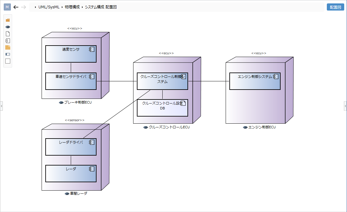
Layouts can be used to describe the physical structure and layout of the system. This page describes the operations for using the layout plan in the following order.
- Place the layout plan
- Define a node
- Define associations
Place the layout plan
Follow the steps below to place the layout plan.
Operation procedure
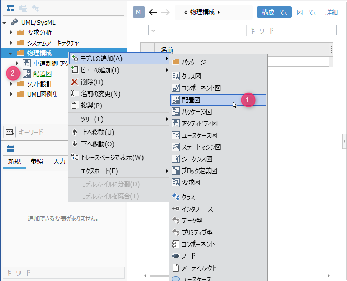
- Select a package in the model navigator and click Add Model> Deployment Diagram in the context menu.
- The layout will be placed on the child elements of the selected package.
Define a node
To define a node, do the following:
Operation procedure
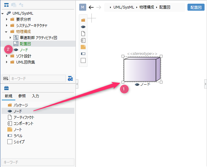
- Drag and drop [Node] from the toolbox to the displayed layout plan.
- A new node is added as a sibling element of the displayed layout.
Elements that can be added from the toolbox
In the layout plan, you can add the following elements displayed in the toolbox.
| Icon | Name |
|---|---|
 | Package |
 | Node |
 | Artifacts |
 | Components |
 | Note |
 | Labels |
 | Shape |
Add a stereotype to a node
To add a stereotype, do the following:
Operation procedure
- Select a node.
- Click the Add button in the Basic information> Stereotype field in the Property inspector to see the choices.
- Select a stereotype and press the [OK] button to set the stereotype for the node and display the stereotype in the node shape.
tip
Stereotype choices can be defined in the Detail view of the package model.
tip
You can edit the added stereotype from the layout drawing by following the steps below.
- Double-click the stereotype displayed on the node to enter the edit state.
- If you change the stereotype and confirm the edit, it will be reflected on the layout plan and the stereotype of the node will be changed.
tip
- If you want to display the existing node on the layout plan, you can display it by dragging and dropping the node on the model navigator onto the layout plan.
- You can define the placement on a node by dragging and dropping artifacts and components onto the node shape on the diagram. Artifacts and components defined as placements are added as child elements of the node.
Define associations
To define the association, do the following:
Operation procedure
- Move the pointer over the node you want to associate.
- Drag the [▲] icon displayed on all sides of the node and drop it on the other node.
- A list of associations that can be added will be displayed. Select the association you want to add, and the selected association will be added.
Related that can be added
The following associations are available in the layout:
| Icon | Name |
|---|---|
 | Dependencies |
 | Related |
Add stereotypes to associations
To add a stereotype, do the following:

Operation procedure
- Select a relationship.
- Double-click the grayed out [<< stereotype>>] to enter the edit state.
- When you enter the stereotype you want to set, the stereotype is displayed in the relation of the layout plan, and the stereotype is set in the relation.
tip
You can use similar steps to define associations for artifacts and components.