Activity Diagram
Overview
Activity diagrams can be used to define the flow of control over system execution. This page describes the operations for using the activity diagram in the following order.
- Place an activity diagram
- Define an action
- Define the flow
It also provides the following features to assist in user modeling: These will also be explained in order.
- Validate the model

Place an activity diagram
To place an activity diagram, do the following:
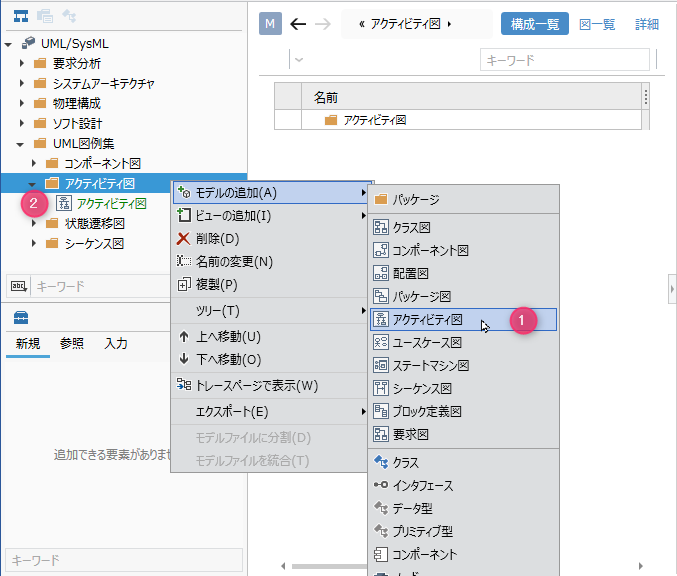
Operation procedure
- Select a package in the model navigator and click Add Model> Activity Diagram in the context menu.
- The activity diagram is placed on the child elements of the selected package.
Define an action
To define an action, do the following:
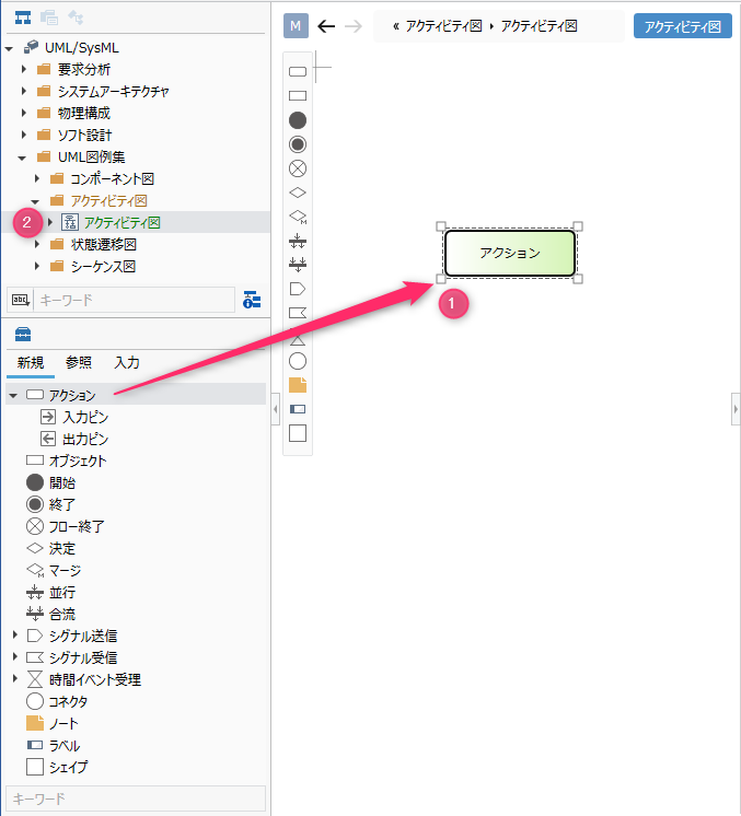
Operation procedure
- Drag and drop Actions from the toolbox onto the displayed activity diagram.
- A new action is added as a child element of the displayed activity diagram.
Elements that can be added from the toolbox
You can add the following elements that are displayed in the toolbox in the activity diagram.
| Icon | Name |
|---|---|
 | Actions |
 | Input Pins |
 | Output pin |
 | Object |
 | Start |
 | Exit |
 | End Flow |
 | Decision |
 | Merge |
 | Parallel |
 | Join |
 | Signal transmission |
 | Signal reception |
 | Accept Time Event |
 | Connector |
 | Note |
 | Labels |
 | Shape |
Arrange the input pin and output pin as port shapes of the following elements.
- Action
- Receive signal
- Signal transmission
- Time event acceptance
Add stereotypes to actions
To add a stereotype, do the following:
Operation procedure
- Select an action.
- Click the Add button in the Basic information> Stereotype field in the Property inspector to see the choices.
- Select a stereotype and press the [OK] button to set the stereotype for the action and display the stereotype for the action shape.
tip
Stereotype choices can be defined in the Detail view of the package model.
tip
You can edit the added stereotype from the activity diagram by following the steps below.
- Double-click the stereotype displayed in the action to enter the edit state.
- If you change the stereotype and confirm the edit, it will be reflected on the activity diagram and the stereotype of the action will be changed.
Define the flow
To define the flow, do the following:
Operation procedure
- Move the pointer over the action you want to associate.
- Drag the [▲] icons that appear on the four sides of the action and drop them on the other action.
Flow that can be added
The following flows are available in the activity diagram.
| Icon | Name |
|---|---|
 | Flow |
 | Signals |
Add a guard condition to the flow
To add a guard condition, follow the steps below.
Operation procedure
- Select a flow.
- Double-click the grayed out [guard] to enter the editing state.
- When you enter the guard condition you want to set, the guard condition is displayed in the flow of the activity diagram, and the guard condition is set in the flow.
Add stereotypes to the flow
To add a stereotype, do the following:

Operation procedure
- Select a flow.
- Double-click the grayed out [<< stereotype>>] to enter the edit state.
- Enter the stereotype you want to set, the stereotype will be displayed in the flow of the activity diagram, and the stereotype will be set in the flow.
Validate the model
The contents verified in the activity diagram are as follows.
- Is there a flow connecting to itself from the control node (decision, parallel, merge, etc.)?
To validate your model, do the following:
Operation procedure
- Click the [UML]> [Verify]> [Check Consistency] button on the ribbon to verify all models.
tip
Click the Home> Model> Check Error button on the ribbon to perform validation on all models in addition to standard validation. Also, when a new flow is added on the activity diagram, the added flow is checked in real time.
Restrictions
- Not compatible with swim lanes.
- The display position of the action pin is different from the UML standard (it is displayed so that it overlaps the node).
- Parallel/merge shapes will be horizontal immediately after addition. In order to make the parallel/merge vertical, the shape needs to be deformed by the resizing operation.
- Interruptable areas, extended areas, and exceptions cannot be described.