View definition of sequence diagram
Overview
Next Design allows you to add an existing model as the lifeline of the sequence diagram or select a message according to the model to which you want to send the message.
For example, you can create a sequence diagram by the following operations.
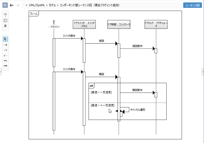
Example of creating a sequence diagram using a component and its input port
- Add [Component] defined as a model as a lifeline.
- When adding a message between components, select the port to send the message from [In Port] provided by [Component].
Example of creating a sequence diagram using a class and its methods
- Add [Class] defined as a model as a lifeline.
- When adding a message between classes, select the method to call from [Method] provided by [Class].
To be able to add a specific type of model as a lifeline, set the type of model that can be associated with the lifeline as the view definition of the sequence diagram. This is called lifeline mapping definition.
To be able to select a message according to the model to which the message is sent, set the fields that can be associated with the message for each model type as the view definition of the sequence diagram. This is called a message mapping definition.
The following describes how to define the view of the sequence diagram in the following order.
- Set the types of models that can be added to the lifeline
- Set message choices for each model type
Set the types of models that can be added to the lifeline
To set the lifeline mapping definition so that you can add a specific type of model as a lifeline in a sequence diagram, follow these steps:
Operation procedure
- Display the target sequence diagram in the editor.
- Click Sequence Diagram> Mapping> Edit Lifeline Setting from the ribbon to open the Edit Lifeline Setting dialog.
- Click the + icon at the bottom right of the Mapping list to open the New Lifeline Mapping dialog.
- Select Class from the Mapping Target pull-down list.
- Click the [...] button of [Data Type] and select the model type (example: component) to be added as a lifeline.
- Change the [Figure] and [Model Name] as necessary, and click the [OK] button.
- Once you have set the lifeline mapping definition, the Toolbox's Reference tab will display the models that you can add as a lifeline.
Set message choices for each model type
To set the message mapping definition so that you can select the message according to the model to which you want to send the message, follow these steps:
Operation procedure
- Display the target sequence diagram in the editor.
- Click Sequence Diagram> Mapping> Message Settings from the ribbon to open the Message Settings dialog, and Mapping will list the types of models you can add to your lifeline. increase.
- Move the pointer to the target field to which the message is associated and click the + icon to open the Message Mapping Definition Settings dialog.
- From the Target Field pull-down list, select the field you want to associate with the message.
- From the Title pull-down list, select the field you want to display as the label for your message.
- Select [Parameter] and [Return type] as required, and click the [OK] button.
- If you want to associate multiple fields, repeat steps 3-6.
- If you set the message mapping definition, you will be presented with choices when you add a message.
note
- Before setting the message mapping definition, it is necessary to set the types of models that can be added in the lifeline mapping definition.