ER diagram view definition
Overview
Next Design allows you to define a view of an ER diagram that can represent the structure of the model and the relationships between the models in a diagram format.
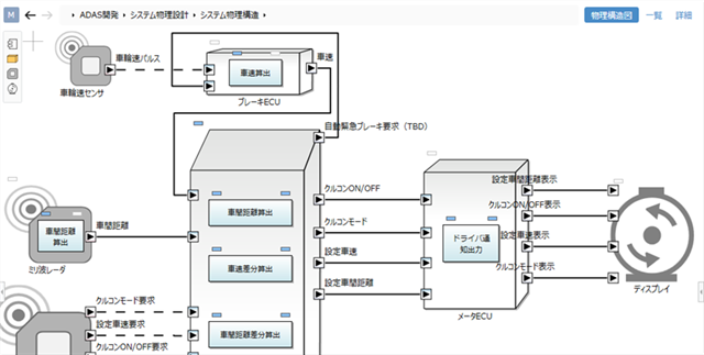
By defining the following notation in the view definition of the ER diagram, diagrams of various designs can be expressed.
- Shape: Shape for each entity
- Connector: Relationship line between entities
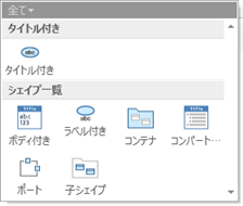
There are the following types of shapes:
| Shape types | Description |
|---|---|
| Title Only Shape | A title is attached to the shape. |
| Title and Description | The body such as the title and description of the figure is attached. |
| With Label | A title is attached to the outside of the shape. |
| Container | You can have related models as nested shapes. |
| Compartment | You can display multiple fields that you specify within a shape. |
| Port | Can be placed on the edge of a shape as a connector contact. |
| Child Shape | Allows related models to be nested shapes. |
There is only one type of connector. By changing the style of the connector, you can add a polygonal line or an arrow.
The following describes how to define a view for an ER diagram in the following order:
- Define a shape
- Define a connector
Define a shape
Add a shape
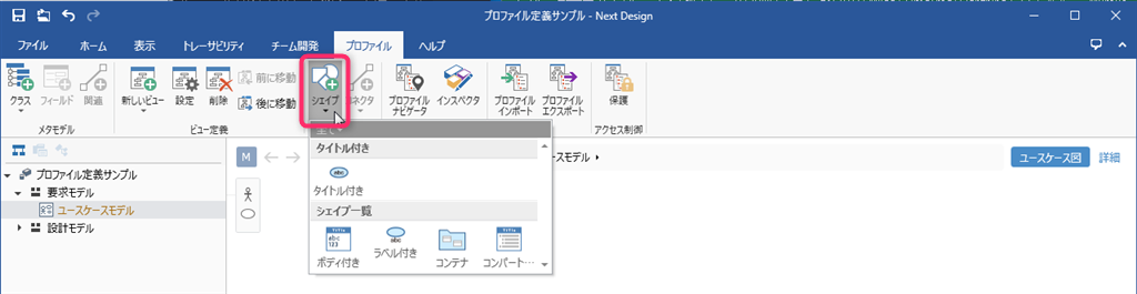
Operation procedure
- For the operating procedure, refer to the following contents.
Quick Start> Profile Definition> Define Diagram View> Add Shape for Each Entity (../../quick-start/profile-definition/define-diagram-view#define-diagram-view--add- shape-by-each-entities)
note
- Of the shape types, [Port] and [Child Shape] cannot be added unless the parent shape is selected. See "Adding Child Shapes" below for more information.
Change the shape type and shape
Operation procedure
- Select the shape you want to change on the view.
- To change the shape type, click Shape> Node> Kind from the ribbon, then click the type from the choices.
- To change the shape of a shape, click Shape> Style> Change Shape from the ribbon, then click the shape from the choices.
Using custom shapes
- In addition to the standard built-in shapes, you can also use your own images as shapes.
- For more information, see FAQ> I want to use images instead of shapes in diagrams.
Attention
- Extra labels (such as the model name) may remain visible after changing the shape type. In that case, delete unnecessary labels according to "Change Shape Label" below.
Change the default shape style
- Change the style of individual models displayed in the diagram
- Change the default style of the shape defined for each entity as the view definition of the diagram
This section describes the latter procedure. For the former, see Modeling Guide> Edit Model> Edit ER Diagram.
To change the default style and size of a shape, do the following:

Operation procedure
- Select the shape you want to change on the view.
- Use the following UI to change the default style of the shape.
- Ribbon [Shape]> [Style]> [Change Shape], [Quick Style], [Fill], [Line], [Font Color]
- Inspector Shape Definition tab> Style> Figure, Color, Border Thickness, Show metamodel icon
- Change the default size of the shape in one of the following ways:
- Resize the selected shape and click the Shape> Size> Set Default Size from Selected Shape button on the ribbon.
- Enter the width in the upper row and the height in the lower row of [Shape]> [Size]> [Default Size] on the ribbon.
- Enter a value in the Shape Definition tab> Default Size> Width, Height in the Inspector.
note
- Changing the default size of a shape does not change the size of the selected shape or an existing shape.
- The shape added after changing the default size will be the default size.
Change the icon of the entity

Operation procedure
- Click View> Pane> Inspector from the ribbon to display the Inspector on the right side of the screen.
- Select the shape you want to change on the view.
- Select Metamodel from the tabs at the top of the Inspector.
- Click Select under Class> Icon and select an icon from the Select icon dialog.
Change the label of the shape
Operation procedure
- Select the shape you want to change on the view.
- To change the field to display in the shape title or body, select the field to display from the Shape> Text> Title or Body pull-down list on the ribbon.
- To change the shape title or body alignment, select [Align Left], [Center], [Align Right] under [Shape]> [Text]> [Title] or [Body] on the ribbon. Click one of to switch.
To add or remove shape labels, do the following from the Inspector:
Operation procedure
- Click View> Pane> Inspector from the ribbon to display the Inspector on the right side of the screen.
- Select the shape you want to change on the view.
- Select Shape Definition from the tabs at the top of the Inspector.
- To add a label, click the + button below the Label list.
- Select [Filelds] and [Layout] in the [New Label] dialog, enter the text when the value is not set in [Hint Text], and click the [OK] button.
- To remove the label, select the relevant line from the [Label] list and click the [-] button below the list.
Delete shape
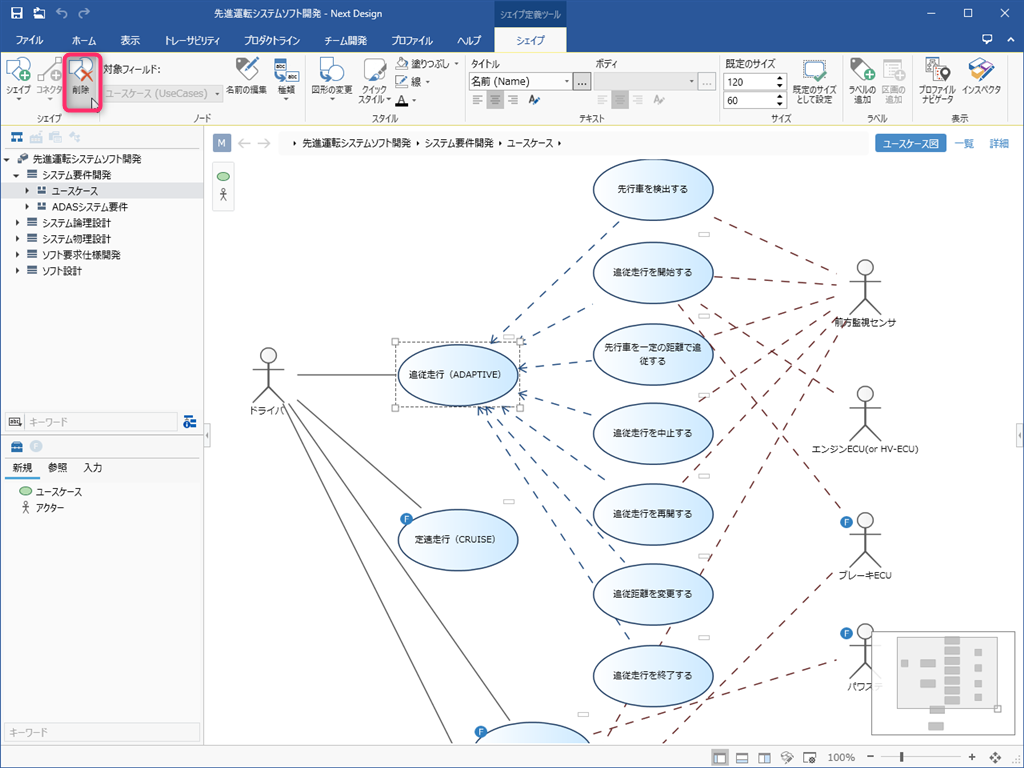
Operation procedure
- Select the shape you want to delete on the view.
- From the ribbon, click Shape> Shape> Delete.
- All the shapes are removed from the view, but the model remains. Add the shapes again and those models will reappear in the view.
Attention
- When you remove a shape from the view definition of the ER diagram, the connector that connects to that shape is also removed from the view definition.
Add a child shape
Operation procedure
- Select the shape you want to have the nested shape on the view.
- Add the child shape in one of the following ways:
- Click Shape> Shape> Shape from the ribbon, then click Child Shape from the shape list.
- Click Profile> Diagram> Shape from the ribbon, then click Child Shape from the shape list.
- In the New Shape dialog, select the field holding the associated model from the Target Field pull-down list and press the OK button.
- You can now drag and drop entities that can be added as related elements from the Tool Box into the shape.
note
- If you have multiple types of entities that can be added as related elements, you need to add a child shape for each of those entities.
Add port
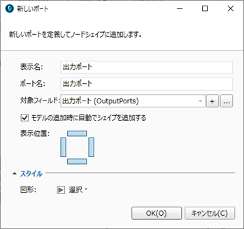
Operation procedure
- Select the shape you want to have the port on the view.
- Add the port in one of the following ways:
- Click Shape> Shape> Shape from the ribbon, then click Port from the shape list.
- Click Profile> Diagram> Shape from the ribbon, then click Port from the shape list.
- In the New Port dialog, select the field that holds the model you want to associate from from the Target Field pull-down list.
- Next, in [Display Location], select the location where the port can be placed.
- Next, select the shape of the port in [Figure] and click the [OK] button.
- You can now drag and drop entities that can be added as related elements from the Tool Box to the edges of the shape.
note
- If you have an input port and an output port, define the two associations in the metamodel and then add a port for each of those associations.
Change compartment parcel
Operation procedure
- Select the shape you want to change on the view.
- From the ribbon, click Shape> Label> Add Compartment.
- In the New Compartment dialog, select the field you want to add from Filelds and press the OK button.
To change the order of the fields displayed in a parcel or remove them from the parcel to hide them, follow these steps from the Inspector:
Operation procedure
- Click View> Pane> Inspector from the ribbon to display the Inspector on the right side of the screen.
- Select the shape with the compartment you want to change on the view.
- Select Shape Definition from the tabs at the top of the Inspector.
- Select the fields listed in [Compartments] and use the [↑] and [↓] buttons at the bottom of the list to change the order, and the [-] buttons to remove them from the partition.
Define a connector
Add a connector
See
Quick Start> Profile Definition> Define Diagram View> Add Connector for Reference Associations Between Entities (../../quick-start/profile-definition/define-diagram-view#define-diagram-view- -add-connector-for-references-between-entities)
To add a reference association between entities and a connector definition at the same time when the reference association between entities is undefined, follow these steps:
Operation procedure
- Select the two models on the ER diagram that you want to connect the related lines by clicking while holding down the ctrl key.
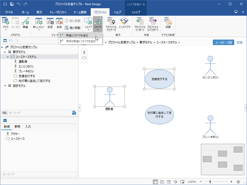
- From the ribbon, click Profile> Diagram> Connector, click ▼, and then click Add Reference and Connector.
- In the New Connector Shape dialog, use Relate From and Relate To to see the relevant direction.
- Next, select [Icon] and set the [Style] item.
- Click the OK button in the dialog to add the reference associations and connector definitions between the entities to the metamodel and at the same time add the association lines on the ER diagram.
Change the default style of the connector
- Change the style of individual related lines displayed in the ER diagram
- Change the default style of connectors defined for each association as a view definition in the ER diagram
This section describes the latter procedure. For the former, see Modeling Guide> Model Editing> Editing ER Diagram.
To change the default style of the connector, do the following:
Operation procedure
- Select the connector you want to change on the view.
- Use the following UI to change the default style of the connector.
- Ribbon [Connector]> [Style]> [Relate From], [Relate To], [Line Type], [Quick Style], [Fill], [Line]
- Inspector Shape Definition tab> Style> Relate From, Relate To, Line Type, Color, Border Thickness, Line Style, Show metamodel icon
Change connector label
Operation procedure
- Select the connector you want to change on the view.
- From the ribbon, click Connector> Add Label.
- Select [Filelds] and [Layout] in the [New Label] dialog, enter the text when the value is not set in [Hint Text], and click the [OK] button.
- Edit the connector field values on the Property tab of the Inspector.
To change or remove a connector label, follow these steps from the Inspector:
Operation procedure
- Click View> Pane> Inspector from the ribbon to display the Inspector on the right side of the screen.
- Select the connector you want to change on the view.
- Select Shape Definition from the tabs at the top of the Inspector.
- To change the connector label, point to the line listed under Label and click the Edit Label button at the right end of the line.
- In the [Setting --Label] dialog, change [Filelds] and [Layout] and click the [OK] button.
- To remove the connector label, select the line listed in Label and click the-button below the list.
Change connector settings
Operation procedure
- Click View> Pane> Inspector from the ribbon to display the Inspector on the right side of the screen.
- Select the connector you want to change on the view.
- Select Shape Definition from the tabs at the top of the Inspector.
- Change the setting items in the [Shape] group.
reference
- For more information on connector settings, see Reference> Profile Settings and Modeling Changes.
Remove connector
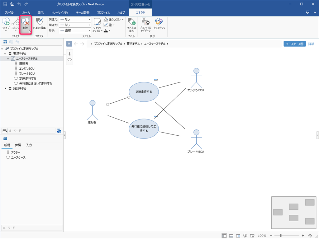
Operation procedure
- Select the connector you want to delete on the view.
- From the ribbon, click Connector> Shape> Delete.
- All the connectors are removed from the view, but the association remains as a model. Add the connectors again and their associations will reappear in the view.