Parametric Diagram
Overview
Parametric diagrams can be used to describe constraints between systems using mathematical formulas, etc., and to perform analysis such as identifying important parameters for performance. This page describes the operations for using parametric diagrams in the following order.
- Place a parametric diagram
- Define constraint properties
- Define associations
Place a parametric diagram
To place a parametric diagram, do the following:
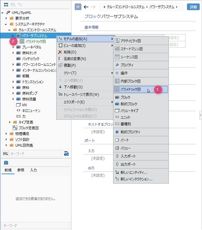
Operation procedure
- Select the block in the model navigator and click Add Model> Parametric Diagram in the context menu.
- The parametric diagram is placed as a child element of the selected block.
Define constraint properties
Add a constraint property
To add a constraint property, do the following:
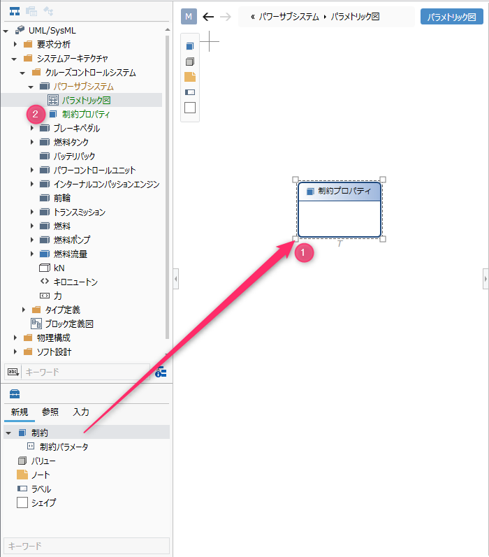
Operation procedure
- Drag and drop Constraints from the toolbox onto the displayed parametric diagram.
- The constraint property is placed as a sibling element of the displayed parametric diagram.
Elements that can be added from the toolbox
Parametric diagrams allow you to place the following elements that are displayed in the toolbox:
| Icon | Name |
|---|---|
 | Constraints |
 | Constraint Parameters |
 | Value |
 | Note |
 | Labels |
 | Shape |
Constraint parameters are placed as port shapes in Constraints (constraint properties), but cannot be added from the toolbox. By setting the constraint block to the constraint property type, the constraint parameters defined in the constraint block are reflected on the diagram.
Add stereotype to constraint property
To add a stereotype, do the following:
Operation procedure
- Select a constraint property.
- Click the Add button in the Basic information> Stereotype field in the Property inspector to see the choices.
- Select a stereotype and press the [OK] button to set the stereotype in the constraint property and display the stereotype at the top of the constraint property shape.
tip
Stereotype choices can be defined in the Detail view of the package model.
tip
You can edit the added stereotype from the parametric diagram by following the steps below.
- Double-click the stereotype displayed in the constraint property to enter the edit state.
- When you change the stereotype and confirm the edit, it is reflected on the parametric diagram and the stereotype of the constraint property is changed.
Set type
To set a type for a constraint property, do the following:
Operation procedure
- Select a constraint in the displayed parametric diagram to display the Property Inspector.
- Click the [+] button of the [Constraints] property, select the constraint block in the displayed finder, and click the [OK] button.
- The constraint property is typed and the constraint shape on the parametric diagram shows the constraint parameters defined in the constraint block as ports.
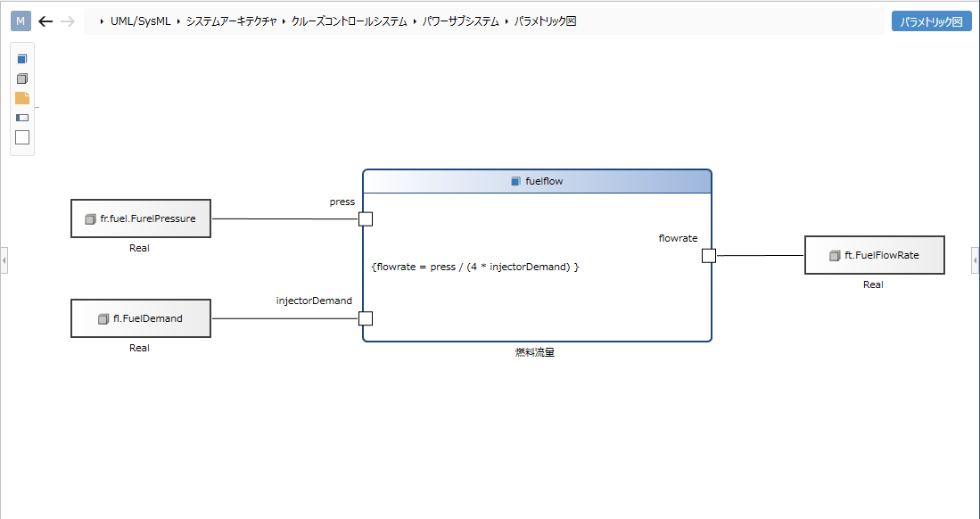
Describe the content (mathematical formula)
To describe the content (formula) in the constraint property, follow the procedure below.
Operation procedure
- Open the sub-editor in advanced mode and select the constraint property in the parametric diagram on the main editor.
- On the sub-editor, enter a formula in the constraint property [Constraint content] and confirm it, and it will be reflected on the parametric diagram.
tip
Normally, variables used in constraint contents (mathematical expressions) are displayed as constraint parameters.
Define associations
To define the association between constraint parameters and values, do the following:
Operation procedure
- Move the pointer over the constraint parameter you want to associate.
- Drag the [▲] icon that appears on all sides of the constraint parameter and drop it on the associated value.
Add stereotypes to associations
To add a stereotype, do the following:
Operation procedure
- Select a relationship.
- Double-click the grayed out [<< stereotype>>] to enter the edit state.
- When you enter the stereotype you want to set, the stereotype is displayed for the parametric diagram association and the stereotype is set for the association.
Restrictions
- The content of the constraint and the type display of the constraint parameter are different from the SysML standard.
- The display position of the constraint parameter is different from the SysML standard (it is displayed so that it overlaps the node).
- The constraint parameter addition operation corresponding to the constraint property cannot be performed (it is automatically reflected by adding it to the constraint block of the type).