Internal Block Diagram
Overview
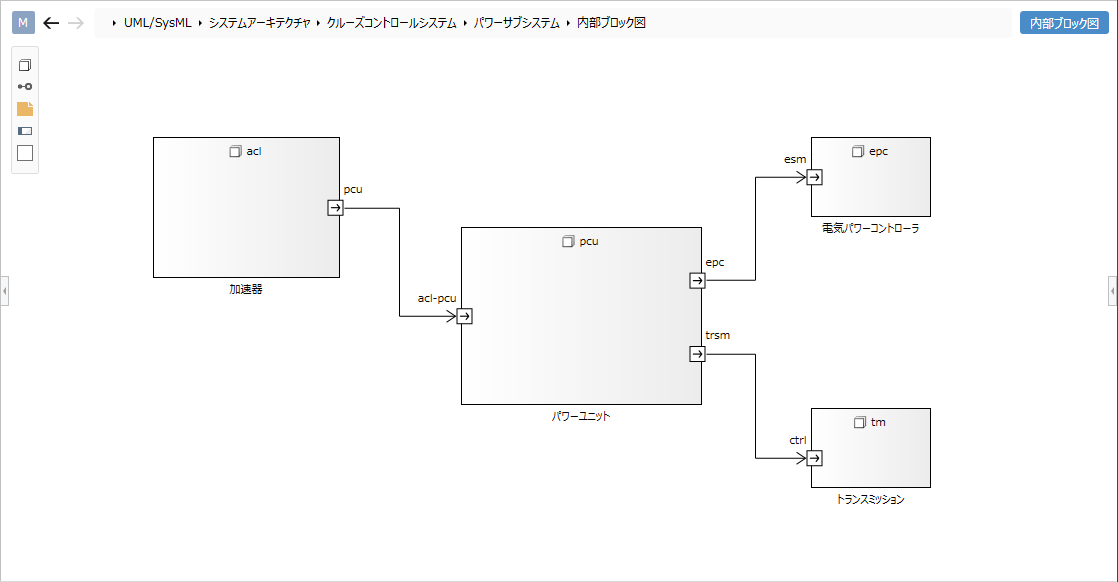
You can use the internal block diagram to describe the relationships between the properties inside the block diagram. This page describes the operations for using the internal block diagram in the following order.
- Place an internal block diagram
- Define a part
- Define a directed connector
It also provides the following features to assist in user modeling: These will also be explained in order.
- Set the display contents
Place an internal block diagram
To place the internal block diagram, follow the steps below.
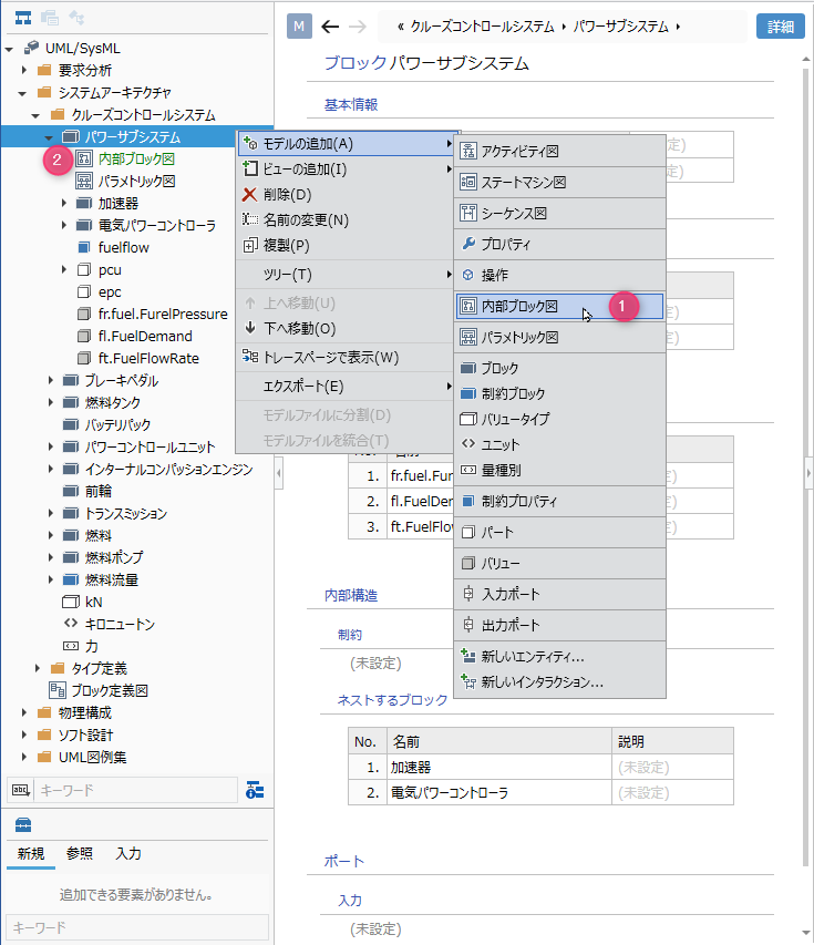
Operation procedure
- Select a block in the model navigator and click Add Model> Internal Block Diagram in the context menu.
- The internal block diagram is placed on the child elements of the selected block.
Define a part
Add a part
To add a part, follow the steps below.
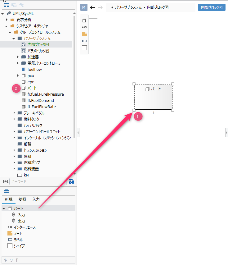
Operation procedure
- Drag and drop [Part] from the toolbox to the displayed internal block diagram.
- A new part is added as a sibling element of the displayed internal block diagram.
Elements that can be added from the toolbox
In the internal block diagram, you can place the following elements displayed in the toolbox.
| Icon | Name |
|---|---|
 | Part |
 | Input |
 | Output |
 | Interface |
 | Note |
 | Labels |
 | Shape |
Inputs and outputs are arranged as port shapes for the following elements, but cannot be added from the toolbox. By setting a block for the part type, the input/output of the block will be reflected on the figure.
- part
Add a stereotype to a part
To add a stereotype, do the following:
Operation procedure
- Select a part.
- Click the Add button in the Basic information> Stereotype field in the Property inspector to see the choices.
- Select a stereotype and press the [OK] button to set the stereotype for the part and display the stereotype for the part shape.
tip
Stereotype choices can be defined in the Detail view of the package model.
tip
You can edit the added stereotype from the internal block diagram by following the steps below.
- Double-click the stereotype displayed in the part to enter the edit state.
- If you change the stereotype and confirm the edit, it will be reflected on the internal block diagram and the stereotype of the part will be changed.
tip
To display an existing part on the internal block diagram, drag and drop the part on the model navigator onto the internal block diagram.
Set type
To set the type for a part, follow the steps below.
Operation procedure
- Select a part in the displayed internal block diagram to display the Property Inspector.
- Click the [+] button in the [Type] property, select the block in the displayed finder, and click the [OK] button.
- The part is typed and the input and output defined in the block are displayed as ports in the part shape on the internal block diagram.
tip
When editing the input/output of a part, it is automatically reflected by editing the input/output of the block set for the part type.
Define a directed connector
To define a directed connector, do the following:
Operation procedure
- Move the pointer over the output port.
- Drag the [▲] icon that appears outside the output port and drop it on the input port.
Edit the multiplicity of directed connectors

Operation procedure
- Select the directed connector.
- Double-click the grayed out [*] to enter the editing state.
- When you enter the multiplicity you want to set, the multiplicity is set for the directed connector and the multiplicity is displayed for the directed connector in the internal block diagram.
Edit the relevant end name of the directed connector

Operation procedure
- Select the directed connector.
- Double-click the grayed out [-] to enter the editing state.
- When you enter the related end name you want to set, the related end name is set in the directed connector and the related end name is displayed in the directed connector in the internal block diagram.
Add stereotypes to directed connectors
To add a stereotype, do the following:
Operation procedure
- Select the directed connector.
- Double-click the grayed out [<<stereotype>>] to enter the edit state.
- When you enter the stereotype you want to set, the stereotype is displayed on the directed connector in the internal block diagram, and the stereotype is set on the directed connector.
Set the display contents
By making the elements on the internal block diagram a simple display, you can display only the information you are interested in without changing the state of the model. For example, to simplify the related visibility, follow the steps below.
Operation procedure
- Display the internal block diagram for which you want to switch the display.
- From the UML Diagram tab in the Inspector, toggle the check box for the Visibility checkbox in the Relationship group.
Elements that can switch the display
You can switch the display of the following elements in the internal block diagram.
| Category | Elements |
|---|---|
| Common | Stereotype |
| Relationship | Visibility |
Restrictions
- Port addition operation corresponding to the part is not possible (it is automatically reflected by adding it to the type block).