I want to place a model that is not directly related to one ER diagram.
The ER diagram is designed by arranging and designing the child elements and referenced models that make up the model to be edited. In addition, you can place models in one ER diagram that are not directly related to the design of the model to be edited.
For example, requirements analysis process use cases and design process components are designed in different processes, so they are not listed side by side in the same design result. However, if you want to see the connections between design outcomes between processes, you can express the relevance by placing them on the same ER diagram.
Next Design typically specifies a field for the shape when adding a shape definition to the ER diagram, but you can specify any class instead of the field. This allows you to place use cases and components designed in different processes on a single ER diagram.
The following is an example of arranging components that are the design results of different processes in Use Case Diagram Defined by View in Quick Start. This is explained in the following order.
- Add component shape definitions to use case diagrams
- Place an existing component in a use case diagram
- Add a connector definition that represents the relationship between the use case and the component
Add component shape definitions to use case diagrams
You need to add a shape definition to be able to place the model on the ER diagram, but to add a shape definition for a component that is not directly related to the use case diagram, do the following:
Operation procedure
- Prepare a project with a set of use case and component profiles according to Quick Start.
- Select Use Case Model in the Model Navigator to display the Use Case Diagram view.
- From the ribbon, click Profile> Diagram> Shape, then click the type of shape you want to add.
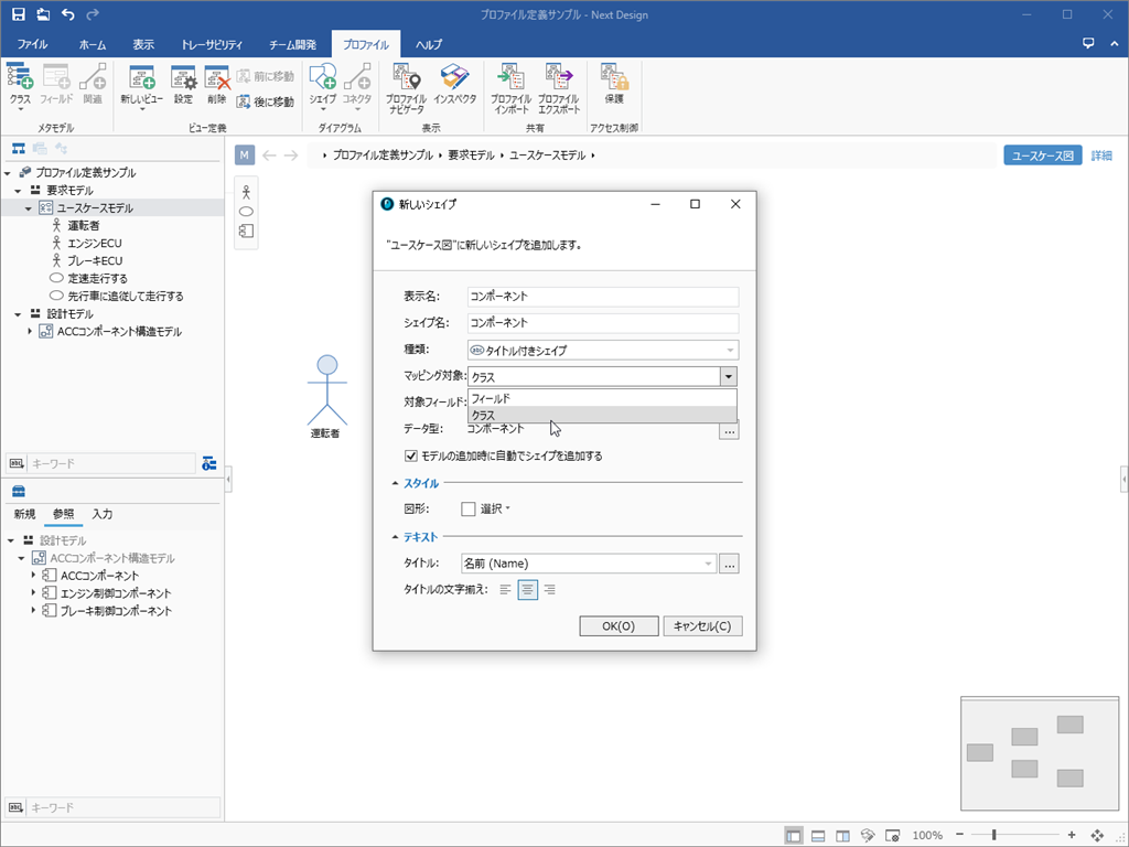
- Set the following items in the New Shape dialog.
- Under Mapping Target, select Class.
- Click the [...] button on the far right of [Data Type] and select [Component] from the list of entities.
- Under Style, under Figure, select the shape shape.
- Click the OK button in the dialog to add the Component icon to the toolbox.
Place an existing component in a use case diagram
To place an existing component in a use case diagram after adding the component's shape definition to the use case diagram, follow these steps:
Operation procedure
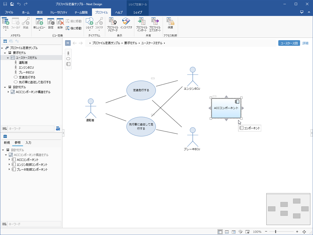
- Select Use Case Model in the Model Navigator to display the Use Case Diagram view.
- Switch the toolbox under the Model Navigator to the Reference tab to list the existing components that you can place in the use case diagram.
- Drag and drop an existing component displayed on the Reference tab of the toolbox onto the use case diagram.
note
- If the existing model does not appear on the Reference tab of the toolbox, use one of the following methods to redisplay the model to be edited.
- Switch views in the model editor
- Toggle selection in Model Navigator
Add a connector definition that represents the relationship between the use case and the component
To connect a related line between a use case and a component in a use case diagram, add a connector definition as in the next step.
See
[Profile Definition Guide> View Definition> ER Diagram View Definition> Define Connector> Add Connector](../profile-definition-guide/view-definition/er-diagram-view-definition#er-diagram -view-definition--define-connector)