Define diagram view
Overview
Profiles allow you to define the structure of your model as a metamodel, as well as the representation of your model as a view. The diagram view definition defines the following as a representation of the model:
- Entity shape
- Relationship line (connector) between entities
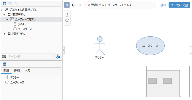
In the following, let's define a diagram view that allows you to edit the Use Case Model in UML use case diagram format as follows:
- Add a view to the Use Case Model defined in the metamodel
- Add a shape for each Actor and Use case entity defined in the metamodel
- Added a connector for the reference association between [Actor] and [Use case] defined in the metamodel.
Image of diagram view to define
1. Add a view to your model
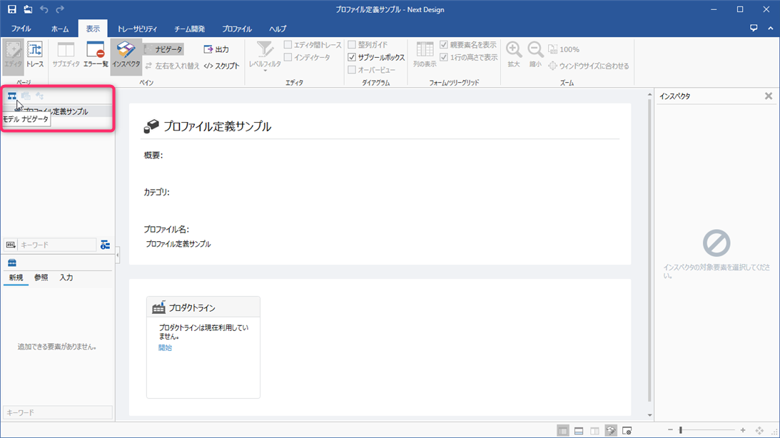
Switch to the model edit screen
View definition is done on the model edit screen used for modeling. First, select [Model Navigator] from the selector at the top of the navigator to switch to the model edit screen.
Add use case model for view definition
To start the view definition, you need to add one model for view definition in the model navigator. Follow the steps below to add a use case model for view definition.
Operation procedure
- Right-click [Profile Definition Sample] displayed at the top of the model navigator, and click Click Add Model> Request Model from the context menu Add [Request Model] directly under the project.
- Right-click on the added Request Model Click Add Model> Use Case Model from the context menu Add a use case model for the view definition.
- You have now added the Request Model> Use Case Model needed to start the view definition.
Add ER diagram view to use case model
To be able to edit the Use Case Model in use case diagram format Follow these steps to add an ER diagram to the Use Case Model view.
Operation procedure
- Under Model Navigator, select Use Case Model.
- From the ribbon, click Profile> View Definition> Add View, then click ER on the diagram. The New Diagram dialog is displayed.
- Enter [Usecase Diagram] as the display name and click the [OK] button to add the view options in the upper right corner of the editor editing area.
2. Add shape for each entity
To be able to add a model to the added diagram view, add a shape to the view and Assign the entities defined in the metamodel.
This section describes how to add the following shapes and assign entities so that you can add Actors and Use cases to your view.
| Shape Type | Entity | Figure |
|---|---|---|
| [With Label] Shape | [Actor] | UML/SysML Shapes> Actors |
| [Title Only Shape] Shape | [Use case] | UML/SysML Shapes> Use Cases |
Operation procedure
- From the ribbon, click Profile> Diagram> Shape, then click the type of shape you want to add.
- In the New Shape dialog, under Target Field, select the entity you want to assign.
- Next, set the following items in the dialog.
- Under Style, under Figure, select the shape shape.
- Under [Text], [Title] or [Body], select the field to be displayed in the shape and the type of [Alignment].
- Click the [OK] button in the dialog to add the corresponding icon to the toolbox and add it to the view.
3. Add connector for reference association between entities
To connect the model components on the ER diagram view with related lines, add a connector to the view. Assign the associations defined in the metamodel.
Here, the relation line corresponding to the reference relation of [Actor] and [Use case] associated in the metamodel is shown. Here are the steps to make it possible to connect on the ER diagram view.
Operation procedure
- Add Actor and Use case on the ER diagram view.
- Hold down the ctrl key and click to select Actor and Use case.
- From the ribbon, click Profile> Diagram> Connector, click ▼, and then click Add Connector Exist Reference.
- In the Relationship Class of the New Connector Shape dialog, select Actor to Use Case Reference as the association to assign. Click the [OK] button.
- Now that you have added connectors, you can associate those entities on the diagram.
note
- Connectors must be defined for each association defined in the metamodel.