Derive the model
Overview
Next Design not only handles various models related to the software to be designed in one project, but also By creating a new model with an existing model as input, the trace information between the models is automatically recorded. You can save the trouble of adding trace information later.
The design act of creating a new model by inputting an existing model is called model derivation.
The following describes the metamodel definitions and model derivations required for model derivation in the following order:
- Define the derivation association in the metamodel so that the [Component Structure Model] can be derived from the [Use Case Model].
- Derivation of [Component Configuration Model] by inputting [Use Case Model]
- Add trace information between existing models
Image of derivation-related definition
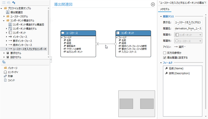
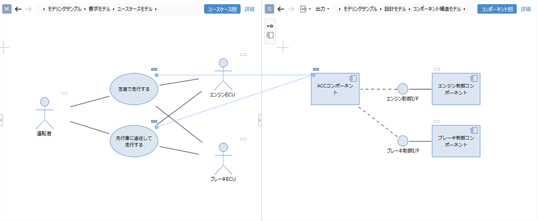
Image of model derivation and tracing
1. Define derivation associations in the metamodel
To derive the Component Structure Model from the Use Case Model and to be able to connect trace lines, follow these steps to define the derivation relationships between the entities.
- Define the metamodel and view of the [Component Structure Model] to be derived.
- Define derivation association between the entities of [Use Case Model] and [Component Structure Model]
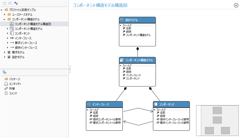
1.1 Define metamodels and views for component structure models
Define the metamodel of [Component structure model] to be derived by referring to the following class diagram.
Operation procedure
- Refer to Quick Start> Profile Definition> Define Metamodel above for the procedure.
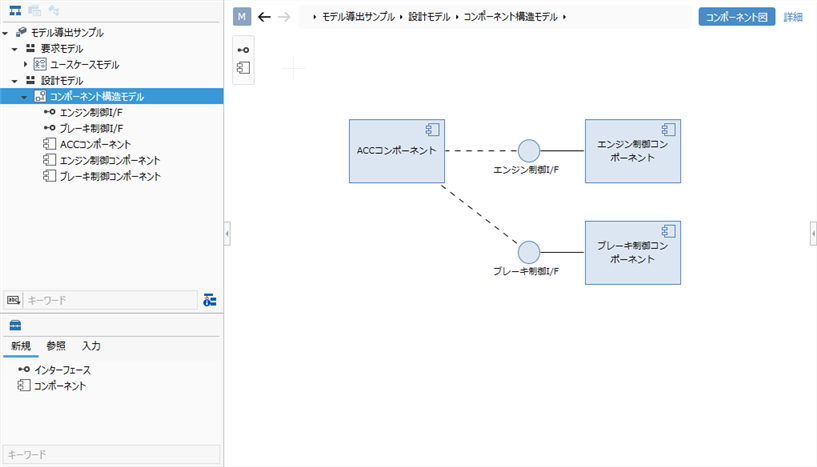
Define the diagram view of the Component Structure Model with reference to the following screen image.
Operation procedure
- Refer to Quick Start> Profile Definition> Define Diagram View above for the procedure.
1.2 Define derivation relationships between use cases and components
To define a derived association between the Use Case Model and Component Structure Model entities, use a class diagram as you would a reference-related definition.
For now, we'll create a new class diagram that defines the derivation associations and only show the associated entities.
| Entity to derive | Entity from which to derive |
|---|---|
| Component Structure Model> Component | Use Case Model> Use Case |
Operation procedure
- Add a class diagram to your profile and enter Derivation Related Diagram as the name.
- Add the existing entity that connects the derivation association to the class diagram from [Profile Navigator].
- Establish a derivation relationship from the entity to be derived to the entity from which it is derived.
- By defining the derivation relationship, you can derive the model and add trace lines.
You have now defined a metamodel for the Use Case Model that has Actors and Use cases as components, and a metamodel for the Derivable Component Structure Model.
2. Deriving components from use cases
To take an existing model as input and derive a new model along with the trace information, follow these steps:
- Display two models side by side
- Create a model using the components of the input model
2.1 Display two models side by side
Add model
Add the [Component Structure Model] to be edited from the model navigator as when adding the [Use Case Model].
Model to be edited: [Modeling sample]> [Design model]> [Component structure model]
Operation procedure
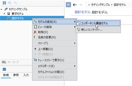
- First, right-click on the project displayed at the top of the model navigator and click on it. Click Add Model> Design Model from the context menu Add Design Model to the first level.
- Right-click the added Design Model and click Click Add Model> Component Structure Model from the context menu Add the model to be edited.
- When you add a model in the Model Navigator, the model is displayed in the main editor and ready for editing.
Show model in sub-editor
To display the sub-editor on the right side of the screen and display the [Use Case Model] that is the input for model creation, follow the procedure below.
Operation procedure
- Click View> Pane> Sub Editor on the ribbon.
- Select Input from the Switch Display Mode pull-down list at the top of the sub-editor.
- Select Use Case Model from the pull-down list that appears additionally to the right.
- If you want to swap the positions of the sub-editor and the main editor, click View> Pane> Swap Left and Right on the ribbon.
2.2 Create a model using the components of the input model
To take an existing model as input and derive a new model along with the trace information, drag and drop the components of the input model as follows:
Operation procedure
- Move the pointer over a component of an existing model and drag the + icon that appears in the upper right corner.
- Dropping on the derived model adds components to the model and at the same time adds trace lines that represent the derivation relationships between the models.
3. Add trace information between existing models
To add trace information between existing model components, drop them on the [○] icon that appears in the upper left of the model component you are dragging.
Operation procedure
- Move the pointer over a component of an existing model and drag the + icon that appears in the upper right corner.
- Drop it on the [○] icon displayed in the upper left of the existing model to which you want to attach a derivation association.
- When dropped, a trace line representing the derivation association is added between the existing model components.