BasicSamples Package
Overview
- This is a sample project that allows you to check the basic functions of Next Design.
- All design data included in this sample is fictitious.
- The samples are intended for the reference purposes only and we disclaim any warranty, whether express or implied, such as without limitation, marketability or fitness for a particular purpose.
note
- There are two packages depending on the edition you are using.
- BasicSamples Package for Enterprise Edition
- BasicSamples Package for Professional Edition
- The difference between the two packages is the presence or absence of data on product line development. Projects containing product line development data cannot be opened in Professional Edition.
Package contents
| File Name | Category | Description |
|---|---|---|
| ADAS_Software_Development.iproj | Sample project | It is a sample with the theme of Advanced Driver Assistance System and Software development. |
Overview of ADAS Software Development project
- This is a sample project that shows an example of how to design from vehicle system design to software design.
- It can be used for reference of metamodel and view definition, confirmation of modeling operation, etc.
Profile definition
- From the profile navigator, you can check the metamodel definition of "vehicle system software development".
- Detailed settings of profile elements (metamodel and view definition) can be confirmed from the inspector.
Metamodel overall structure
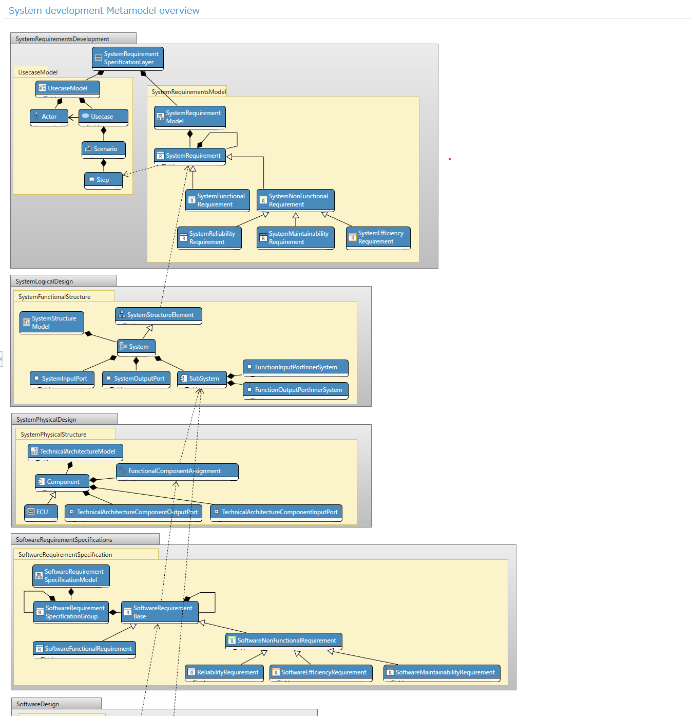
- In the "Overview of in-vehicle system software development metamodel" class diagram, you can grasp the overall structure of the metamodel.
- You can check a series of system design processes such as system requirements development, system logic design, and system physical design, and software requirements development based on it, and design contents up to software design.
Metamodel structure of each process
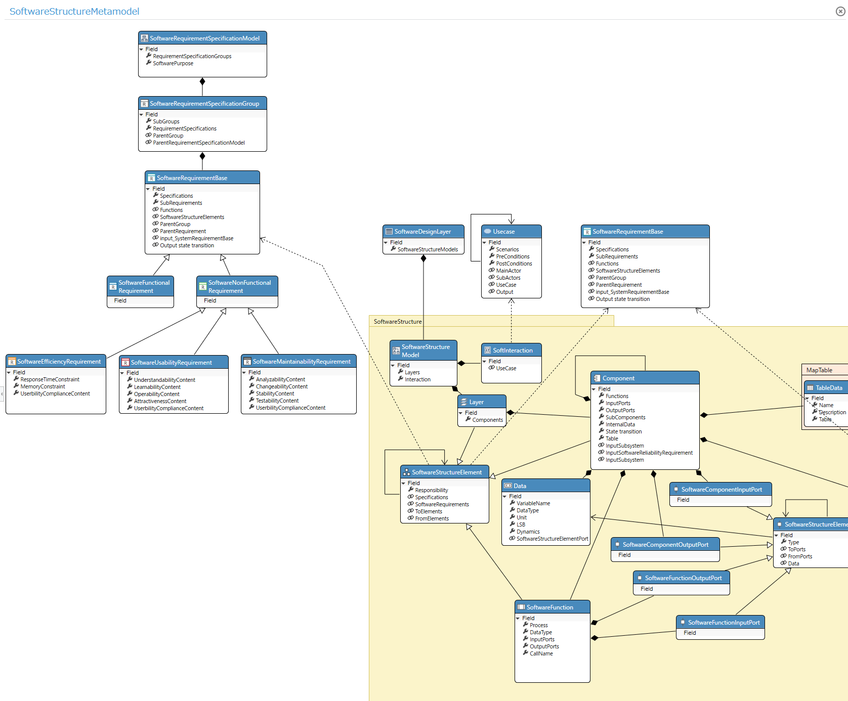
- You can also check the elements, attributes, and derivation relationships to be designed in each process.
- In the above figure, you can check the relationship between the contents to be defined as software requirement specifications and the software components derived from the requirements.
Model design
- From the model navigator, you can see a modeling example with the theme of "auto cruise control" development.
Design example: System requirement design
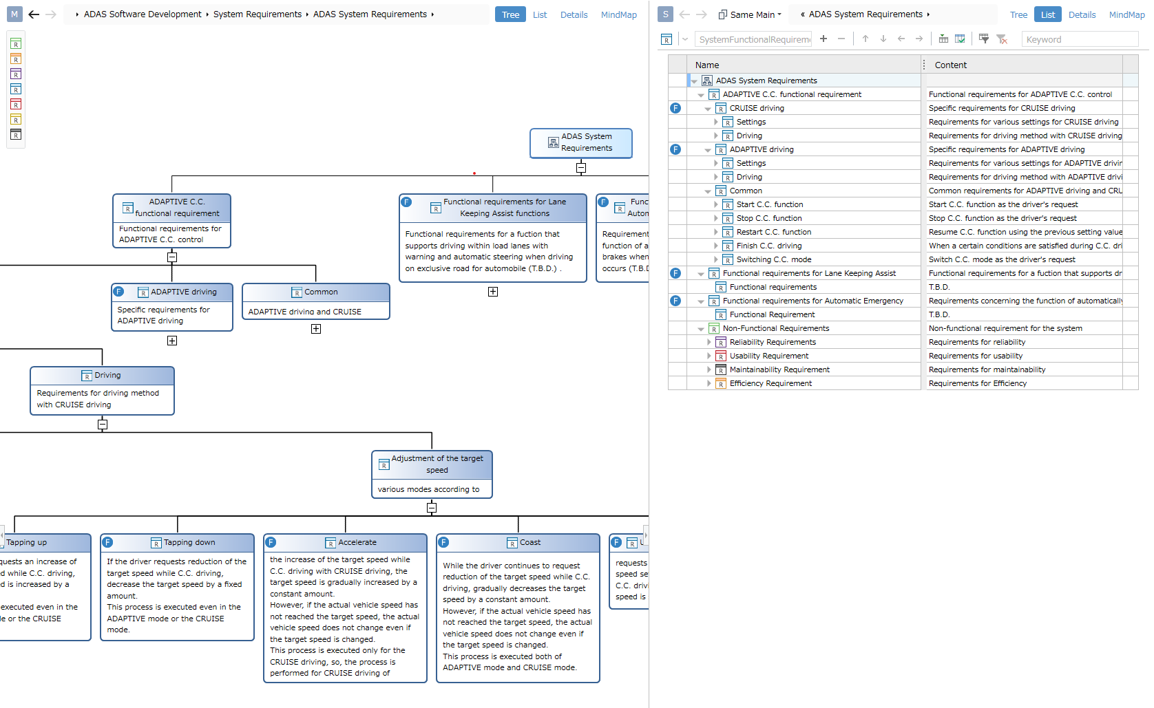
- System requirements can be designed hierarchically.
- The figure shows the same model in different views.
- On the left of the figure is an example of defining a view for a tree diagram.
- On the right of the figure is an example of defining a tree grid form view.
Design example: System logic design
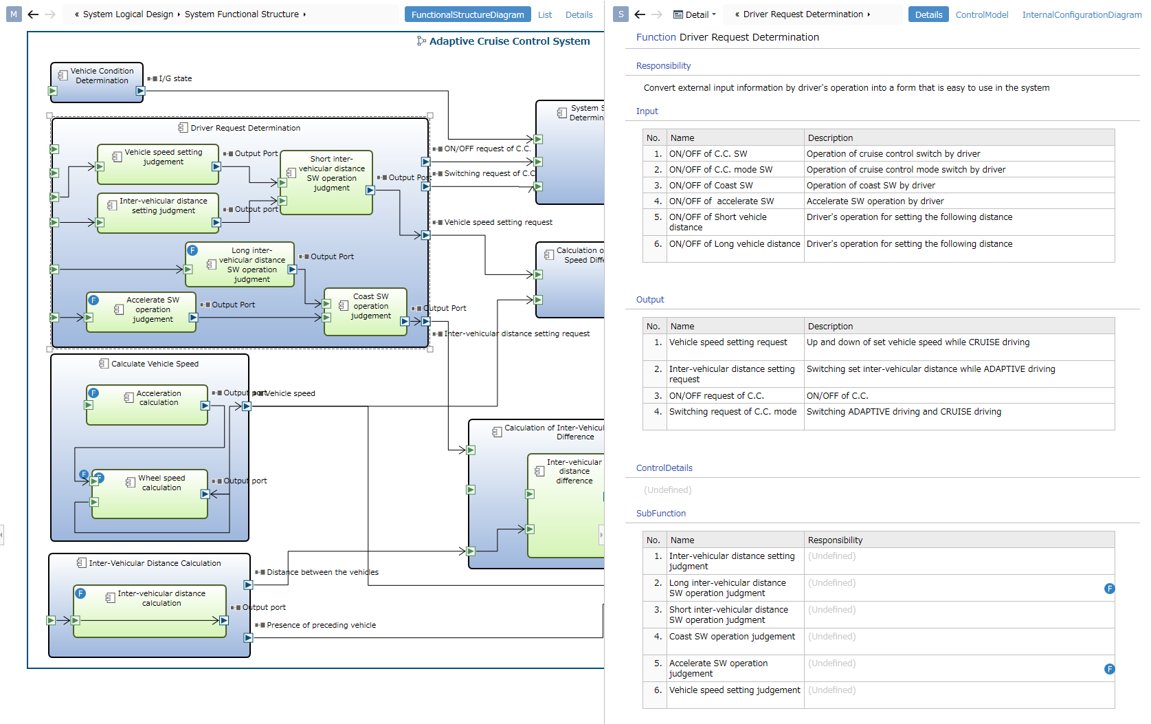
- You can design the system and functions, and its input/output.
- The left side of the figure is an example of defining a view of an ER diagram. The system is defined by the container shape, and the input/output ports are defined by the port shape.
- Select an element on ER diagram to see details in the sub editor.
- The right side of the figure is an example of defining a document form view.
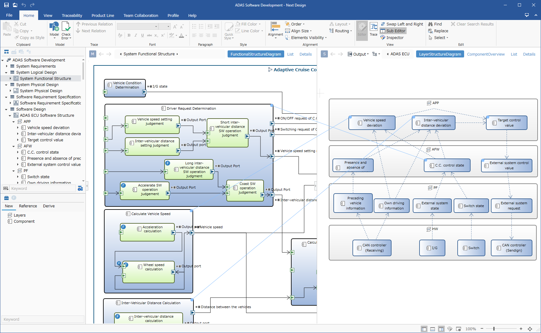
Design example: Software design
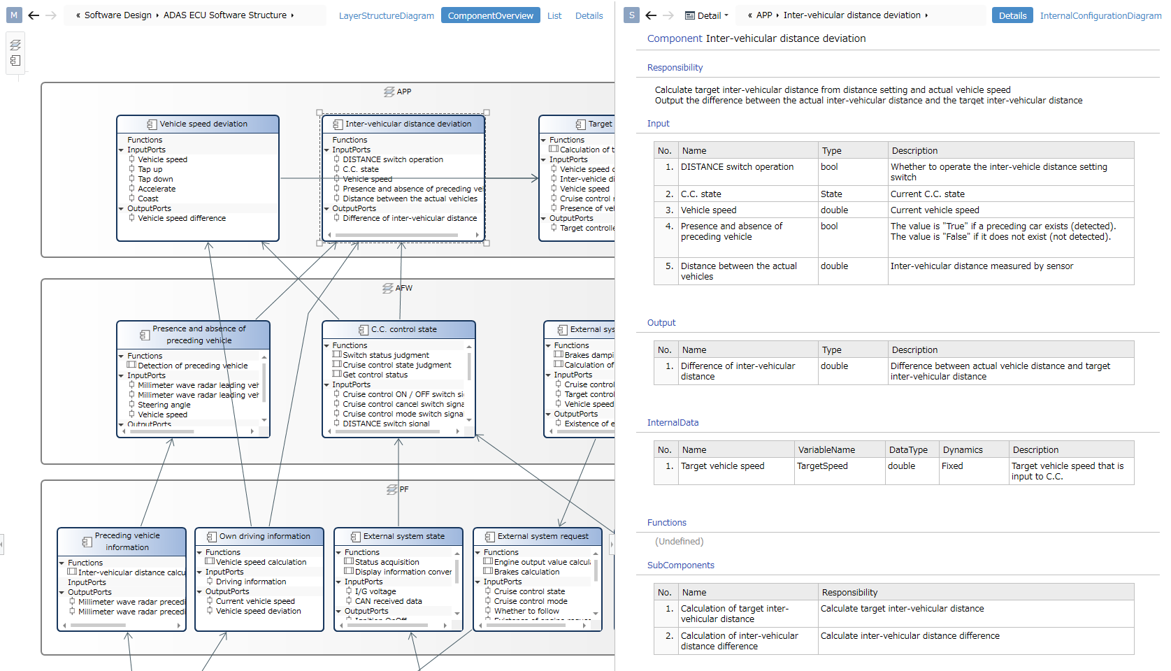
- You can design the layer structure of the software and the components within the layer.
- The left side of the figure is an example of defining a view of an ER diagram. Components are defined by compartment shape, and partitions are defined to display functions and I/O ports.
Design example: Trace display between editors
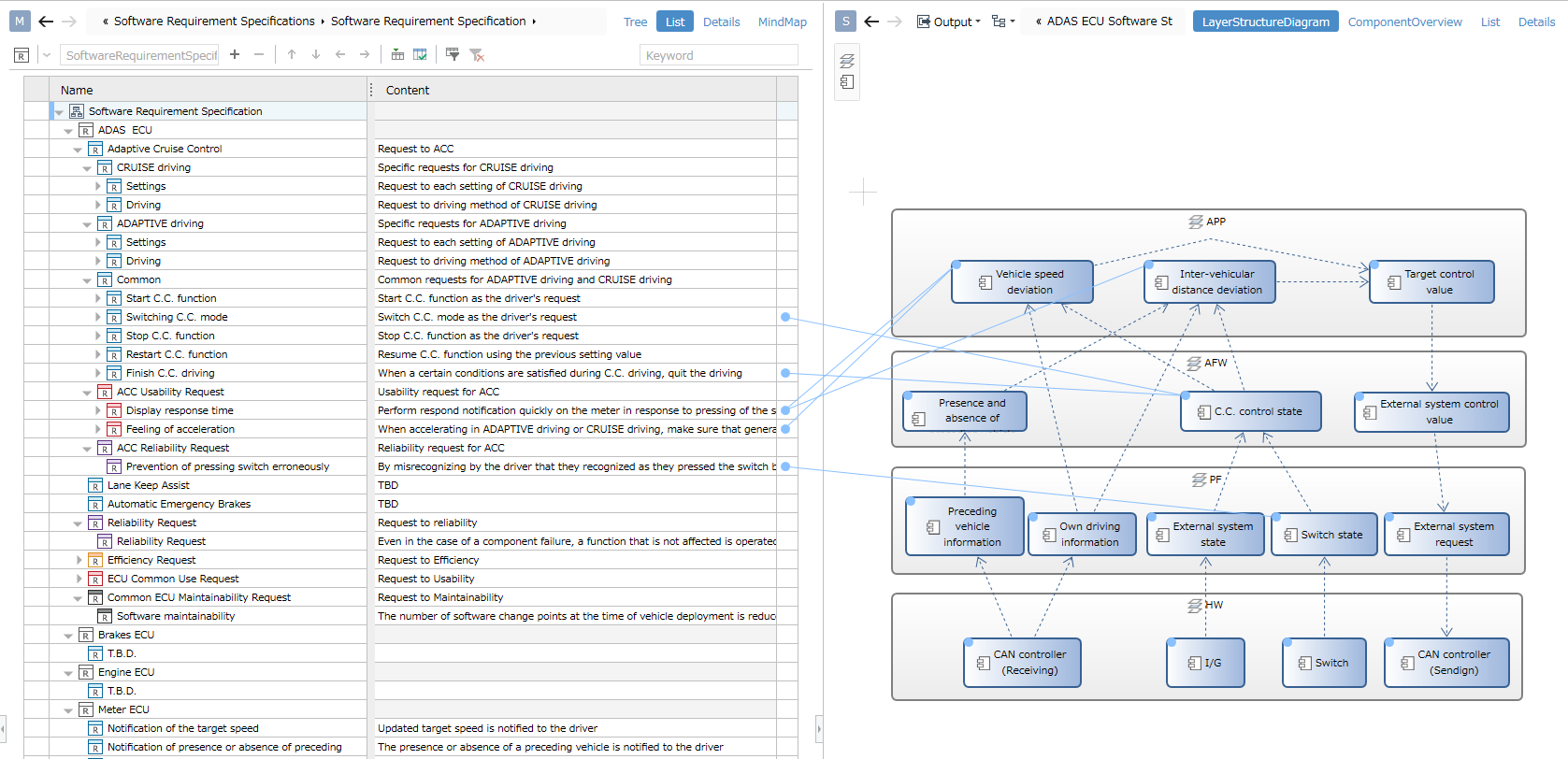
- You can set/check the trace of upstream model and downstream model on the editor.
- The diagram shows traces for software requirements and software components.
Traceability
Tree
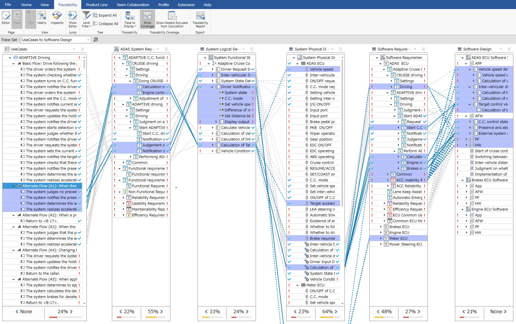
- You can check the trace (related to derivation) from upstream to downstream.
- Selecting a node in the tree highlights elements that are related to derivation, so you can see the scope of your design.
- You can check the coverage rate of traceability. You can also output a coverage report by executing "Print Traceability Report" on the Traceability tab of the ribbon.
Matrix
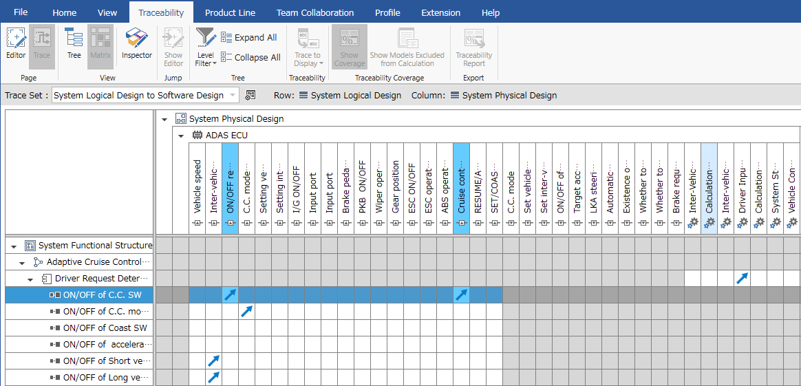
- You can check the trace (derivation related) between the two artifacts.
- Selecting a node will highlight the elements related to the derivation.
- You can set the derivation relation by double-clicking the cell.
Product Line (Only for Enterprise Edition)
Next Design has the product line development function as standard.
Feature design/configuration
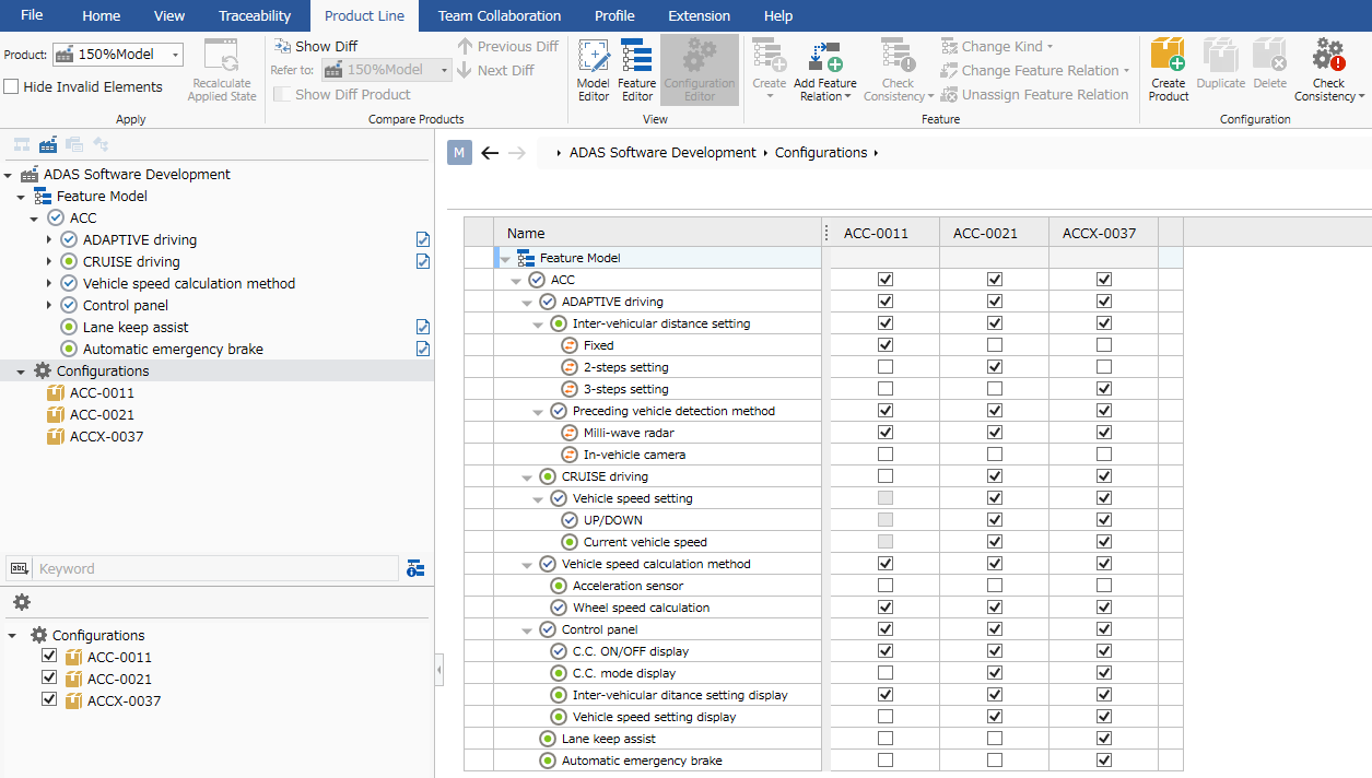
- Feature modeling and product configuration are possible.
- The defined feature can be enabled/disabled by the product by associating it with the model.
When applying the product
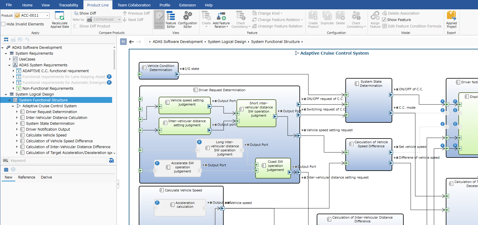
- You can select the product to apply from the Product dropdown on the Ribbon Product Line tab.
- The model that has become invalid due to the application of the product will be displayed in tone down.
- This allows you to design and express functions such as ON/OFF for each destination within one project.